Reflow Oven Controller
Group members: Charles Surianto (Head chef), Musa Charara, Peter Woolsey, Nathan Roorda, Lingxiao TianCourse: ELEC 291: Electrical Engineering Design StudioTable of Contents
- Use of process
- Need and Constraint Identification
- Problem Specification
- Solution Generation
- Solution Evaluation
- Safety & Professionalism
- Detailed Design
Introduction
Reflow soldering is a useful process for soldering surface mount components to a PCB (printed circuit board). Reflow ovens are used to heat up a PCB and its components to a specific temperature profile in order to achieve optimal soldering results. To achieve precise control over the temperature profile, we use a reflow oven controller. This allows the user to set and monitor the temperature profile of the reflow oven.
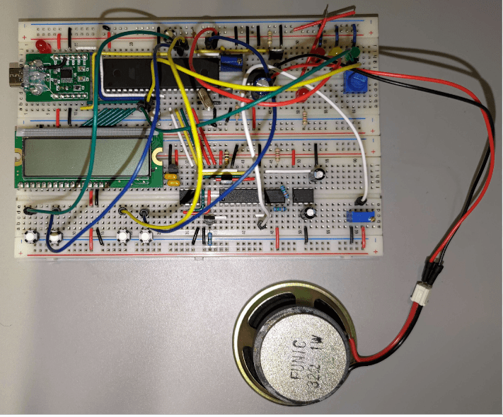
The aim of this project is to design and build a reflow oven controller that is capable of controlling the temperature profile of a reflow oven. The controller is based on the AT89LP51RC2 microcontroller and includes a user interface for setting the temperature profile, as well as temperature sensors for monitoring the temperature of the oven and the PCB. The project involves designing the hardware and software for the reflow oven controller, as well as testing and validating the controller to ensure that it meets the required specifications. The final product is a reflow oven controller that is capable of reliably controlling the temperature profile of a reflow oven, resulting in consistent and reliable soldering results.
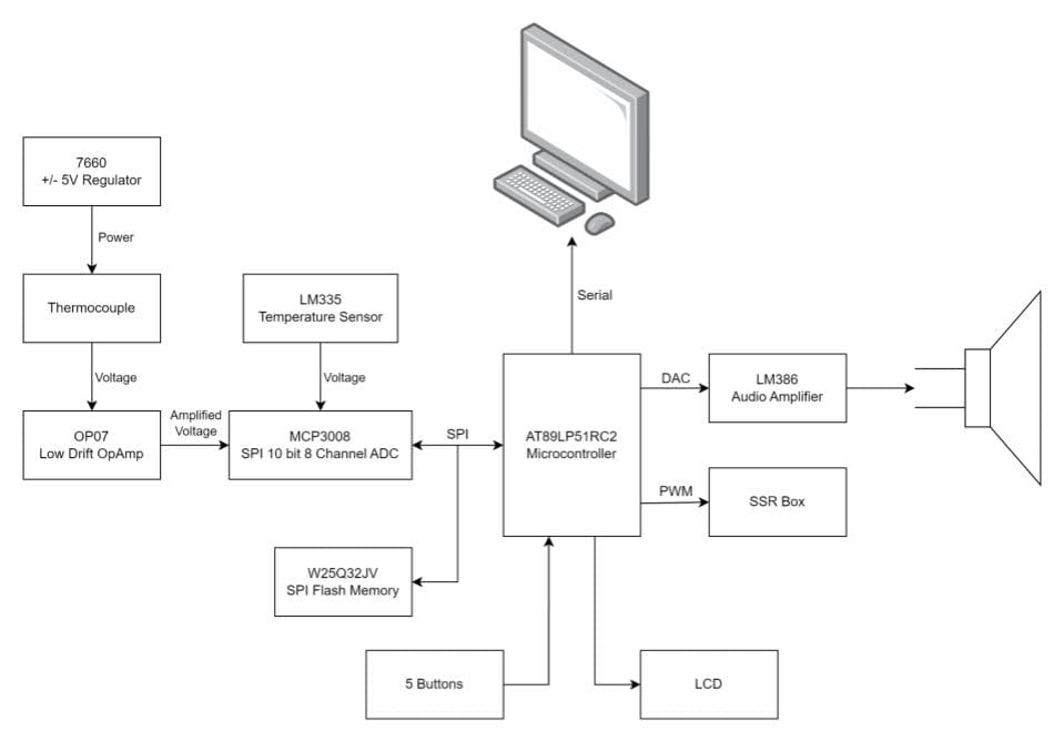
Investigation
Idea Generation
Our team conducted a whiteboard discussion and brainstormed a rough design for our state machines, assembly code strategy, and the overall project structure. We decided on a modular approach and split the project up into three separate subgroups to work on the temperature readings, the sound controller, and the hardware interface. We first proposed different types of controllers we could design rather than relying on a basic approach. We investigated the different types of controllers and settled on trying to implement a PID (Proportional Integral Derivative) controller since it could predict potential errors and adjust accordingly. While ambitious, we realized that we could implement this type of controller promptly before the deadline. To simplify the codebase, we packed our code into macros/functions.
Investigating Design
To identify our best ideas, we thoroughly tested circuit and software designs in small modules. These modules, after being verified that they work, were combined back into our final board. For instance, we tested our simplified thermocouple amplifier circuit by following the course resources provided[1] and designed our circuit to output the predicted voltage gain. To reduce future debugging and to improve our understanding of the circuit, we tested individual components such as the MCP1700[2] and the W25Q32JV SPI flash memory[3] against the specifications in their given data sheets.
Data Collection
We collected data to find the relation between the voltage at the pin and the reading of the ADC which can be seen at Appendix D. We then fed the voltage obtained from excel into a formula from the LM335 datasheet to get the cold junction temperature. As for the hot junction temperature, we utilized its material property as a K-type thermocouple.
Data Synthesis
We used K-type thermocouple wire with a sensitivity of approximately 41 µV/°C to detect the temperature in the reflow oven. The voltage difference was amplified by the Op-Amp in which we chose a 300k and 1k ohm resistor to produce a voltage gain of 300. The output of the Op-Amp will be sent to MCP3008 ADC which the AT89LP51RC2 can read from, and convert to a temperature reading with the following formula,

where ‘GAIN’ is our Op-Amp voltage gain.The output voltage of LM335[4]:

where TO is the reference temperature in Kelvin and T is the measured temperature in Kelvin. The data then can be accessed by AT89LP51RC2 through the SPI bus.
Anaylsis of Results
Our team appraised the validity of conclusions through extensively testing the functionality of our controller and the reflow oven. We encountered oven and microcontroller limitations regarding the accuracy of the thermocouple readings in the oven and the accuracy of the calculations made on the microcontroller. For different locations in the oven, the temperature readings were not consistent. To attain the most accurate temperature, we positioned the thermocouple probe in the center of the oven where the PCB was placed. We also encountered rounding errors in our microcontroller calculations caused by the use of integer operations. This caused a sharp edge in the slope of the temperature readings to display in our temperature profile. For future improvements to our reflow oven controller, we plan to use a more advanced microcontroller that can support floating point operations.
Design
Use of Process
To create our overall design approach, we first discussed all the main tasks of the project and split them into three main categories: the finite state machine, the audio player, and the temperature sensor. Our group split into three focus groups, designing one of the aforementioned categories. Each subteam would share their ideas and progress to the rest of the team, where we collectively explored the ideas further using whiteboard drawings and voted on which ideas to implement. This approach allowed everyone to focus on specific aspects of the project, while allowing everyone to contribute and have an understanding of the project as a whole.
Need and Constraint Identification
Our stakeholders include anyone who needs to do reflow soldering, such as laboratory technicians, engineering professors and students, and chip manufacturers. Since our design covers a wide range of potential clients, there are many stakeholders’ needs we must account for. First of all, our customers’ safety is paramount, which is why our design must obey the engineering safety code. For this concern, we designed additional temperature safety features to prevent burns. Secondly, since we have a variety of potential customers, we made our user interface intuitive and easy to operate. To inform users of the real time data, we designed a user friendly GUI (Graphical User Interface) where they can input parameters and observe how the actual reflow profile compares to the idealized graph. Lastly, we also adhered to the base requirements as outlined by the Project 1 instruction manual[1].
Problem Specification
Our design met the basic requirements of the project outlined above, but we also specified additional features that increase the functionality of the reflow oven based on the needs of our stakeholders. One of the additional features we added are LED indicators to warn the user if the oven’s inner temperature is high and not safe to touch. Furthermore, to more tightly control error, we made it a priority to have a PID feedback loop, ensuring that reflow and soak temperatures don’t exceed 10℃ of variation from the set points.
Solution Generation
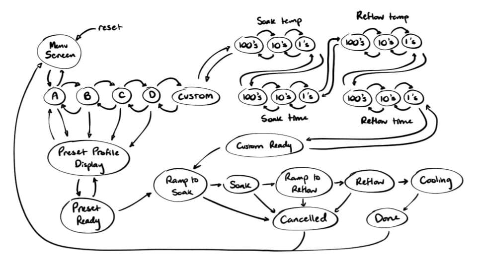
For the firmware finite state machine, we implemented the state diagram shown on figure 2 where each state will have its own run-once part and loop part which will be further explained in the Finite State Machine of Detailed Design section.
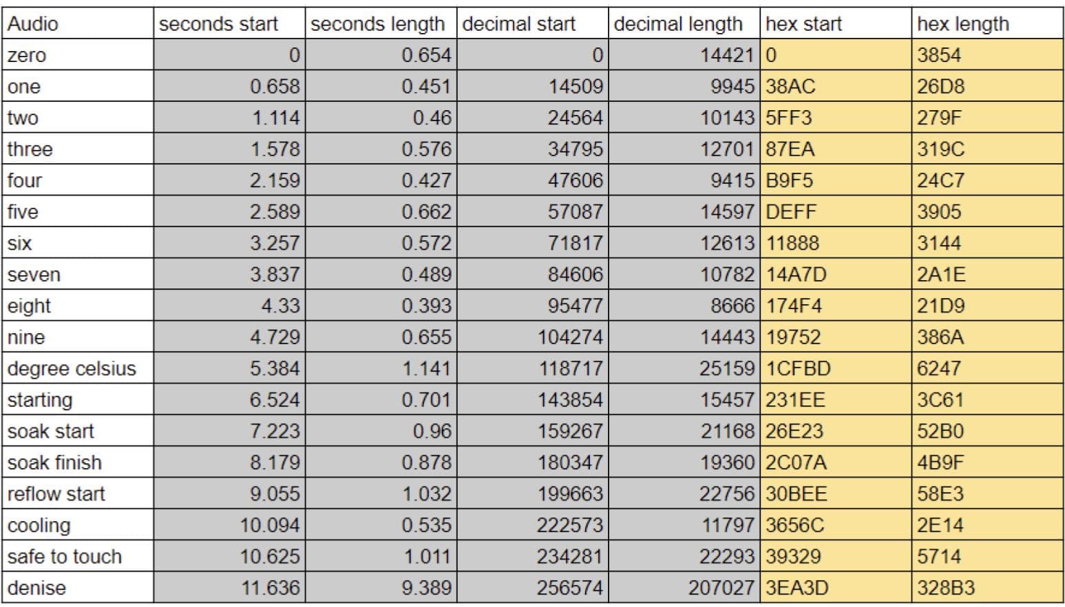
For the sound system, we decided between two options: an implementation that would read out full numbers or a design that reads out one digit at a time. Both options had their own merits computationally and in added functionality; the results of our investigation and decision is detailed below. In addition, we also had to decide between using a macro for our sound functionality or a function. We ended up using a function since our sound’s memory could be located using a table we made which can be seen in figure 3. Furthermore, we saw ways in which the circuit design for the thermocouple amplifier could be simplified from Professor Jesus’s model[1] and still retain the same functionality while being easier to debug and tweak.
Solution Evaluation
We have 5 buttons: left, right, up, down, and start/stop. Up and down increment and decrement the custom parameters, left and right allow for state navigation, and start/stop allows for state initiation or reflow cancellation. We came up with this idea at the beginning and insisted on it because it works well with the finite state machine and the user interface.
For the audio controller, we had the idea of reading the whole number at first but in the end we chose to make it read digit by digit because it would be easier for coding and SPI flash memory management. When implementing the digit by digit design, we developed two methods to index to the correct memory address of the audio clip we were trying to play. The first method we designed was an indexing function that applied integer arithmetic to an input digit to find its index. However, we ran into functionality concerns when using 32 bit math. We also developed an audio controller that relayed upon a case statement to find the index of the audio clip. We found that this method was faster, so it is what we implemented in the final product.
Safety & Professionalism
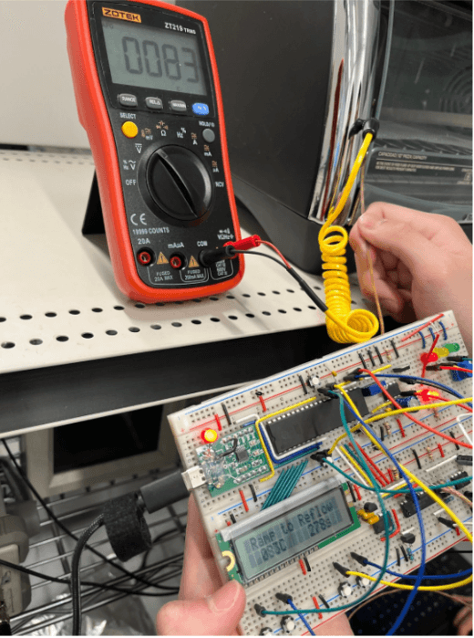
We worked carefully with the high rated power device. When we tested our prototype controller circuit, we constantly supervised the oven when it was on. When we turned off the oven, we were watching the blue LED on the oven to ensure it was turning off. We also made numerous preparations before conducting the actual project. We used multi-purpose paper to test hot spots in the oven to find the best settings and spot for the board; We checked the thermocouple conjunctions and used a multimeter to test and calibrate whether the wire could generate ideal outputs. We also tested individual electronic components, which made it easy for us to troubleshoot our designs. In order to calibrate our temperature sensor, we used a thermometer to test the temperature in the center of the oven.
Detailed Design
Finite State Machine
We utilized a finite state machine with five push buttons and an LCD (liquid crystal display) to support the functionality of our intuitive user interface. The user can choose from four preset reflow profiles, or create their own custom reflow profile. These profiles are selected by using the left and right push buttons to navigate to the desired profile, then pushing the start button to select it. If a preset profile is selected, the state machine will display the preset profile’s unique soak and reflow temperature and time values and wait to confirm that they are ready to start the reflow process. If a custom profile is selected, that state machine directs the user to a screen with the programmable values for the soak and reflow temperature and time values. The user can then use the left and right buttons to navigate each digit of each value, and use the up and down buttons to increment or decrement the value of the desired digit. These values are stored in non-volatile flash memory, allowing the user to reuse the custom settings, even after the circuit has been turned off. Once the desired custom reflow values have been set, the user can move to the ready state. When start is pressed while in the ready state, the oven will turn on with full power and the reflow process will begin. The reflow process starts with the ramp to soak state. Once the temperature reaches the soak temperature, the soak state begins, and maintains this temperature until the specified soak time. Once this time is reached, the oven returns to full power and the ramp to reflow state begins. Once the temperature reaches the reflow temperature, the soak state begins, maintaining this temperature until the specified reflow time. After the reflow time has passed, the oven shuts off and enters the cooling state. Once the oven has reached a temperature less than 60°C, the reflow process is complete, enters the done state, and the LCD indicates to the user that the PCB is safe to handle. We also built in various safety precautions into our finite state machine. If the oven temperature does not exceed 50°C within 60 seconds during the ramp to soak state, the oven will turn off and the state machine will enter the canceled state. Additionally, at any point during the reflow process, the user can press the start/stop button to stop the turn off the oven and move to the canceled state. During either the done or canceled state, the state machine will return to the menu after 30 seconds, or when the start button is pressed. Once in the menu state, the user can repeat the process again.
Sound system
We first started by building the sound portion of the circuit shown in the project documents. We used this as a starting point to test out whether our .wav sound worked. We made a separate circuit for the sound system so we could test it separately and rapidly got it working. After debugging and testing the sound, we realized how tedious it would be to implement a sound system which reads out whole numbers. Instead, as mentioned before in the report, we decided to read out the numbers digit by digit since this would save space in memory as well as make the required assembly code cleaner and more efficient. We first tested out reading out digits using a macro that computes the location of memory that needs to be played by giving the macro the digit that needs to be read as input. We achieved this by splicing the audio clips into equal lengths of 0.5 seconds. Later on, we were required to play out longer audio clips such as the names of certain reflow stages as well as playing background music. This meant we needed to find a solution which could locate audio clips that aren’t necessarily equally spaced in length. We achieved this by creating a function which checks for which clip that needs to be placed by checking the identification number of the clip. After providing this parameter, we would call the function for which there are multiple case statement blocks responsible for playing out each sound. Each block has the memory value hard coded based on the image in figure 3.
Thermocouple & Op Amp circuit
The input voltage of the Op-Amp circuit comes from the K-type Thermocouple wire. The original voltage ranges from 40 micro volts to 10 millivolts. We noticed the output voltage could not enter the saturation voltage zone so that our ideal voltage gain could be ranged from 300 to 350. For convenience, we chose two 150k ohm resistors and one 1k ohm resistor to create a gain of 300, and optimized the original Op-Amp circuit using three resistors which have the same effects.
The Op-Amp chip OP07 needs +5V and -5V dual power supply. For the +5V voltage, we used regular power supply and for the -5V ,we used the LMC7660 which also needed +5V voltage power supply and two 10 microFarads capacitors.On the MCP3008 chip, channel 1 reads the voltage of the LM355, and channel 6 reads the voltage from the output of Op Amp. We also used an averaging algorithm to deal with the received data to mitigate the noise during the measurement, which makes our data more accurate.
Python features
Firstly, we made a starting interface in which users can choose to proceed or exit. If the user chooses to proceed, an input-prompt interface will pop up. Users can enter pre-set times and temperatures of the soaking and reflow stages. The system will then wait for the user to enter ‘space’ on the keyboard to start plotting the real time temperature versus time graph. This requires the user to press the start button on the circuit board at the same time so that the plot can match the ideal curve we expect. After the reflow process and plotting of both the actual and idealized curves are complete, we designed the program to output the time over reflow, the maximum temperature reached during reflow, maximum temperature over the reflow temperature, as well as the maximum temperature under reflow. We choose to report these values as its imperative for the user to know, for instance, the maximum temperature the oven went above the specification and if that may cause damage to the PCB they are soldering. Knowing these parameters will allow the user to better understand the capabilities and limitations of our product and more closely modulate the process for their needs.
LED indicators
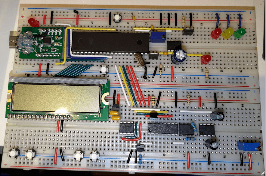
We designed a three-color led system to indicate whether the reflow oven is on, off, or if it is safe to handle the oven. At the start, the green light will turn on. As long as the temperature is under 60℃, the green light will be triggered. Once the process starts and the temperature surges up, the red LED will be on until the cooling phase in which the yellow light is on. After the temperature goes down below 60℃, the green light will be on again.
Solution Assessment
To test the pass-fail requirements, we tested to ensure that each feature was effective. We used this method for the user input, sound, and safety features. For granular requirements, we needed to implement other testing measures. In order to improve our SSR controlling accuracy, we developed a benchmark that evaluates how accurate the PID controller was able to match the ideal reflow curve. This benchmark would return the maximum overshoot and undershoot of the ideal curve, the maximum temperature reached, and the time over the ideal reflow temperature. In combination with the ideal curve in the Python graph, this allowed us to see which parts of the cycle were out of specification. This allowed us to calibrate the coefficients as well as confirm our confidence in the final product.
Life-Long Learning
Although everyone in our group has different experience and skill sets, we found that the majority of the tasks in our project require us to use knowledge learned in previous courses or something new which we needed to self-learn. We found that CPEN 211 proved to be helpful for the assembly programming parts of the project and for understanding the microcontroller’s architecture, especially those that directly affect the way we code. We also found ELEC 221 to be quite useful for the Python portion of the project since we needed to use some of its libraries such as NumPy and MatPlotLib. Lastly, our knowledge of ELEC 201 material helped us design the Op-Amp circuit and debug the whole project circuit as a whole.
Even though a significant part of the project required knowledge previously learned in courses, many portions of the project required us to do our own research, one of which is how to implement a PID controller. We watched videos and browsed websites online to learn about PID controllers. Two courses that could have helped with this part of the project are ELEC 341 and ELEC 441 which talk about PID controllers more in depth. Moreover, we self-taught git version control and used Github to further make our collaboration more productive and to have backup copies of our code. For this reason, CPEN 421 is a course that could have been useful for organizing our coding design approach and organization. Some takeaways our group took from this project are to always refer to datasheets of the components and chips we use and understand it decently before beginning to code in assembly. We also realized that one members code is another members debugging job. To avoid confusion while debugging, we must put informative comments on the code and update each other about changes we make or are going to make.
Conclusions
The design of our reflow soldering oven supports an intuitive user interface, a variety of speaker functionalities, and a comprehensive data logging, allowing our team to solder a variety of SMT components to a PCB. The most notable problem we encountered was merging our modular programs into one final file and debugging our merged code. For future projects, we will be more disciplined in our file management and documentation. We implemented many practical features such as oven state LED indicators to promote safety and user understanding. We also included more technical features like a python script that tracked the progress of the reflow oven and compiled a comprehensive data log for each reflow profile. Our team spent approximately 120 man hours working on our reflow oven project.
References
[1] J. Calvino-Fraga, “Project 1, Reflow Soldering Oven Controller”, University of British Columbia, 2023.
[2] Microchip, “MCP1700 Datasheet”, Microchip technology, 2018.
[3] Winbond, “RS components - W25Q32JV Datasheet”, Winbond, 2017.
[4] Texas Instruments, “LMx35, LMx35A Precision Temperature Sensors”, pg. 8, May 1999 [Revised February 2015].
[5] J. Calvino-Fraga, February 3rd Lecture Slides: Project 1 - Reflow Oven Controller, University of Columbia, 2023.
Bibliography
RealPars, “What is a PID controller,” Youtube, December 2018.